
 Cart
Cart
A building automation system allows automated control of HVAC systems, enabling greater comfort, reliability and energy savings.
But how is it these systems control with such precision, leading to these benefits? One key component is the PID Loop.
A PID loop is a control strategy used in many types of process control systems. PID stands for proportional, integral and derivative. In building automation systems, PID loops are used to maintain precise control of temperature, pressure, flow, or any other physical property within the system. A PID loop, also referred to as a control loop, consists of physical components, such as sensors, dampers, valves, and a loop controller. In BACnet devices, the loop controller takes the form of a loop object within a BACnet controller.
For an example, let’s look at a BACnet control loop that is typically found in a fan coil unit. In this loop, zone temperature is controlled with a valve that is opened or closed to change water flow through a coil. Air flowing through the coil is warmed or cooled to raise or lower the temperature in the room or zone.
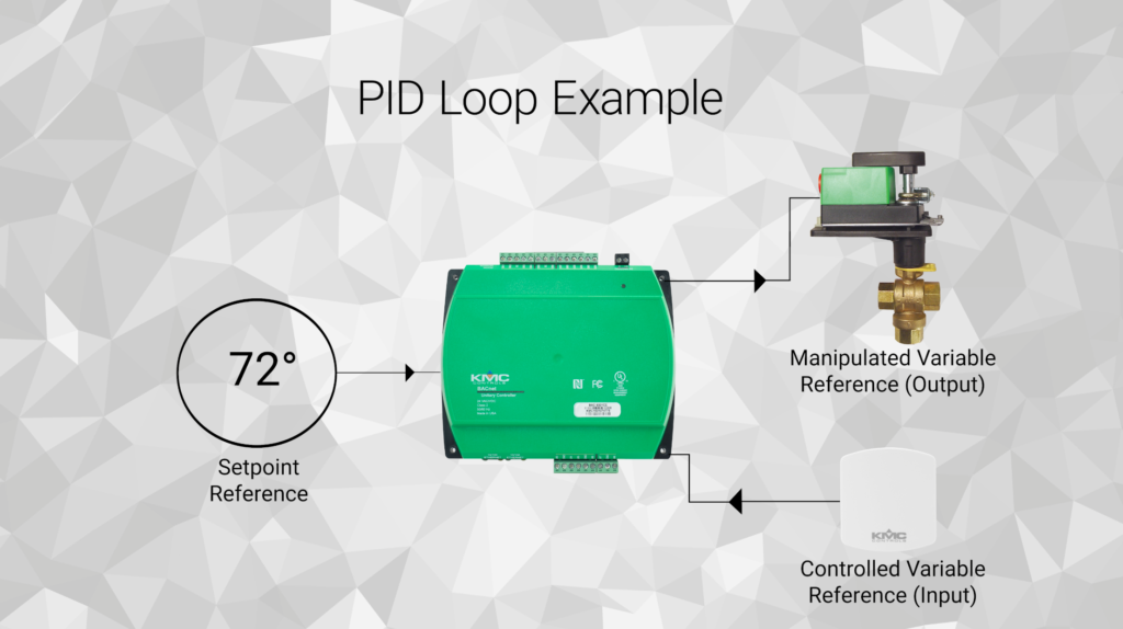
The zone setpoint is represented by the BACnet loop object’s setpoint reference property and is fixed within the controller at a set temperature (i.e. 72 degrees). The output of the loop controls the valve through the BACnet loop object’s manipulated variable reference property. The zone temperature sensor is represented to the loop with the BACnet loop object’s controlled variable reference property and provides feedback to the loop.
When the zone temperature does not match the setpoint, the loop commands the valve to open or close until the zone temperature matches the setpoint.
Now that we know what pieces are involved in our control loop, let’s break down the four-step process running inside the control loop.
The loop maintains control of either a flow, pressure or temperature by the following:
- First by sensing a condition such as a zone temperature, air flow or duct pressure by using the appropriate sensor for the process.
- Next, comparing the measurement of the current condition to the desired setpoint. The setpoint may be a fixed value maintained in either the loop object or value object or from a user input device such as a thermostat.
- Then, responding as the control algorithm within the loop object reacts to any error that may exist by generating a corrective control signal.
- Finally, adjusting by using the corrective control signal to command a device such as a valve, heater or damper to produce a change in the current condition.
The four steps of sensing, comparing, responding and adjusting continuously operate in the PID loop. Loops are more efficient and, if used correctly, will automate control of heating and cooling zones with a high degree of accuracy.
This is just the surface of how PID loops work. To see more in-depth information on PID loops check out our PID Loop webinar here.